
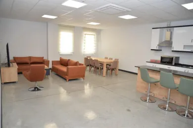
The Smart Grids Laboratory enables real-time computer simulations for a wide range of research and applications in electrical power systems, supporting the development of computable and controllable scientific techniques and technological ideas. The laboratory has the infrastructure to produce solutions for smart home systems, smart industrial and automation applications, and renewable energy applications. Examples of the various applications covered by the Smart Grids Laboratory include:
Smart Home Automation,
Smart Lighting Systems,
Smart Security Systems,
Smart Heating and Energy Solution Systems,
Design and Communication of Smart Relays,
Smart Home Automation and Energy Management,
Smart Grid Demand Response Management,
Management of Electrical Energy Generated by Solar Panels,
Energy Management of Electronic Devices
Through this laboratory, researchers are able to develop smart systems by combining home appliances, smart meters and large-scale systems with internet-based systems, other software and databases. At this point, using intelligent analysis systems for power systems, researchers can experimentally implement solutions such as:
Demand management,
Integration of the maximum possible number of renewable energy sources,
Energy saving and reduction of unit price,
Efficient use of energy resources for generation and consumption
and similar solutions.
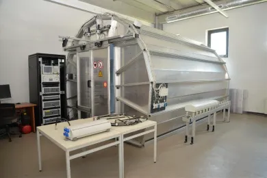
In the Antennas and Propagation Laboratory, performance tests can be carried out on transmitting and receiving antennas and devices used both indoors and outdoors. Passive intermodulation tests, a capability that is in short supply in our country's industry, can also be conducted in this laboratory. This work attracts considerable interest from telecommunications companies. In addition to passive intermodulation tests, VSWR and isolation tests are also performed in the laboratory. By improving the performance of antennas, the fundamental building block of communication technologies, the aim is to provide uninterrupted and high-speed data transfer. As operators choose antennas that pass the tests with high scores, the goal is to deliver faster mobile internet and uninterrupted calls. The performance of transmitting antennas, which form the basis of the high-speed mobile data transfer systems currently provided by 3G and 4.5G technologies and whose capacity will be increased in the near future with 5G technology, is of great importance. Transmitters must deliver data at the highest possible speed, be affected as little as possible by environmental conditions and cause the least possible harm to human health. To this end, a test environment shielded from external signals has been created in the laboratory, where all kinds of signal-emitting devices are tested. For example, the Antenna Test Chamber creates an isolated area in which antenna tests can be carried out. It blocks incoming electromagnetic signals, preventing the equipment under test from being affected by them. At the same time, it prevents the strong electromagnetic waves generated during testing from escaping the test environment.
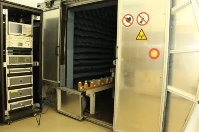
The network analyser applies a signal of known value, amplitude and phase to the input of the system under test and analyses the system response at its output. It operates in the 0.1-1.2 GHz range. It contains one signal generator and two receivers. It can be used to analyse how much the generated signal is distorted and delayed by the system under test.
The intermodulation analyser is used to analyse the intermodulation characteristics of passive components such as connection points, antennas and cables. The intermodulation characteristics of these components are highly important in building communication infrastructures and in providing fast and uninterrupted communication. The instrument contains a two-channel, 20W signal generator and filters at different frequencies. By generating signals at these frequencies, it tests their effect on passive components.
In this laboratory, which will provide hands-on experience for Faculty of Engineering students, Electrical and Electronics Engineering students in particular will gain skills by carrying out tests in the field of communication technologies. The Antennas and Propagation Laboratory, one of our university's leading projects in the field of engineering, will contribute to the training of engineers who will work in the telecommunications industry and thus to a well-qualified workforce.
Laboratory Equipment:
Antenna Test Chamber - Agilent Technologies Network Analyzer:
Laboratory Facilities:
Antenna Test Chamber
Network Analyser
Rosenberger Passive Intermodulation Analyser
Laboratory Coordinator: Assist. Prof. Dr. Motuma Muktar ABAFOGI

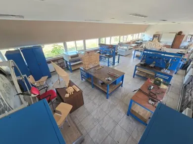
The Barkat Building Production Workshop became operational in February 2025 within the scope of a design and construction project. Work on prototype production and on resolving structural problems within the scope of the project is ongoing. In addition, the workshop focuses in particular on a TÜBİTAK project on timber structures, on scientific research projects and on other R&D activities.
In the workshop, course materials are developed and presented to students in order to reinforce topics that are difficult to grasp in traditional construction techniques and building technology courses offered to the architecture and interior architecture departments. At the same time, workshops, competitions and courses are organized within the context of these courses on the construction, loading and testing stages of structures such as timber houses, timber bridges, timber pergolas (canopies) and brick arches/vaults.
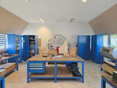
Facilities of the Workshop:
CNC Machine (90x130 cm)
CNC Machine (30x40 cm)
Laser Machine (CUT-ENG CEL 6050)
3D Printer (Bambu Lab H2D Combo)
3D Printer (Raise N2)
Heliodon (solar motion simulation device)
Bench-type machines: horizontal saw, scroll saw, jigsaw, miter saw, router, grinder, lathe, thickness planer, belt sander and pillar drill
Portable equipment: cordless drill, cordless screwdriver, jigsaw, grinder, spray gun, nail/staple gun, compressor, Dremel brand carving, engraving and sanding sets, soldering iron and similar machines
Steel molds for adobe/brick production (4x4x16 cm), precision scales, measuring instruments and similar tools and equipment
In addition to the equipment mentioned above, the workshop houses a wide variety of carpentry tools, solid and engineered timber, as well as building materials such as brick, adobe, cement, lime and sand.
Workshop Supervisor: Assist. Prof. Dr. Muhammed Emin Akyürek
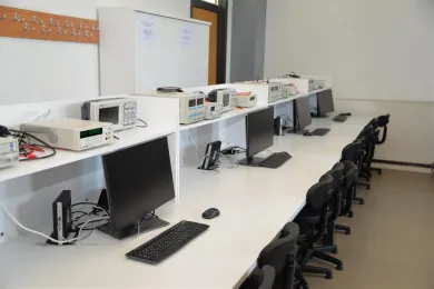
1.1. Fundamentals of Electronic Circuits Laboratory
Electronics is the branch of science that studies the components and systems that process, transmit or store information using electricity. In the Fundamentals of Electronic Circuits Laboratory, students learn the basic electronic components and grasp their operating characteristics. Through applications such as diodes, typical transistor biasing circuits, the biasing of multi-stage amplifiers, common-emitter, common-base and emitter-follower amplifiers, the Darlington pair, the bootstrap biasing circuit, FET and MOS amplifiers, multi-stage amplifiers, linear and non-linear applications of operational amplifiers, power supply circuits and power amplifiers, students are introduced to the science of electronics.
Experiments:
- P-N Junction Diode Characteristics, Forward BIAS & Reverse BIAS
- Zener Diode Characteristics and Voltage Regulator
- Half-Wave Rectifier with and without Filter
- Full-Wave Rectifier with and without Filter
- Transistor CB Characteristics (Input and Output)
- Transistor CE Characteristics (Input and Output)
- Frequency Response of the CE Amplifier
- Frequency Response of the CC Amplifier
- Use of the Transistor as a Switching Element
- MOSFET Characteristics and Its Use as a Switching Element
- Frequency Response of the CS Amplifier
- Frequency Response of the CD Amplifier
Laboratory Facilities:
- Oscilloscopes,
- Power supplies (AC & DC)
- Multimeters
- Diodes
- Zener diodes
- BJT transistors
- FET, MOSFET transistors
- Multisim, Proteus
Laboratory Coordinator: Assist. Prof. Dr. Mohammed JOUDA
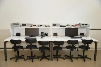
1.2. Digital Electronics Laboratory
Digital electronics is based on Boolean algebra and deals with the design and operation of electronic systems by defining voltage levels as "1" and "0". This laboratory covers topics such as number systems and codes, Boolean algebra and logic gates, logic functions and simplification techniques, combinational logic circuits, arithmetic operations and circuits, multifunction circuits, code converters and encoders, MUX and DEMUX circuits, flip-flops and data registers, synchronous counter circuits, asynchronous counter circuits, special counter circuits, counter circuits and their applications, and shift registers.
Experiments:
- Deriving the Truth Tables of Logic or Universal Gates Using TTL Integrated Circuits
- Design and Applications of Binary-to-Gray and Gray-to-Binary Code Converters
- Design and Applications of Half/Full Adders and Subtractors Using Logic and/or Universal Gates
- Design of Multiplexers, Demultiplexers, Encoders and Decoders
- Design and Implementation of 1-bit and 2-bit Magnitude Comparators
- Verification and Implementation of the Truth Tables of RS, JK, T and D Flip-Flops
- Design and Implementation of Shift Registers
- Design and Implementation of Sequence Generators
- Design and Implementation of Asynchronous Counters
- Design and Implementation of Synchronous Counters
- Design and Implementation of Ring and Johnson Counters
Laboratory Facilities:
- Oscilloscopes,
- Power supplies
- Multimeters
- Logic gates
- Universal gates
- Adders
- Encoders, Decoders
- Multiplexers
- Magnitude Comparators
- Flip-Flops
- Push Buttons
- Shift Registers
- 7-Segment Displays
- Asynchronous and Synchronous Counters
- Regulators
- Ring Counters
- Proteus, Multisim
Laboratory Coordinator: Assoc. Prof. Dr. Mohammed VADİ
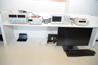
1.3. Microprocessors Laboratory
In the Electronics and Microprocessors Laboratory, which serves both the Electrical and Electronics Engineering and Computer Engineering departments, students can design, simulate, build and test electrical and electronic circuits and carry out experiments with microprocessors and microcontrollers. The aims are to understand the hardware structure of a microcomputer system, to become familiar with computer architectures, to grasp the concepts of microprocessor and microcontroller, to become acquainted with microcontrollers and the various types of PIC microcontrollers, to program PIC microcontrollers and to develop related applications. This is essentially a course on embedded systems presented through the implementation of PIC 16F877a microcontrollers. It starts at the beginner level and takes students to a level at which they possess the skills required to enter professional practice in the embedded world. The course achieves its aims by developing up-to-date fundamental knowledge and skills in both hardware and software development. On the hardware side it involves an in-depth study of both microcontroller design and the circuits and transducers with which the microcontroller must interface. On the software side, C programming is covered.
Experiments: Introduction to PIC16F877A microcontrollers and to the use of the mikroC, Proteus and PICKit2 programs; active-high and active-low button circuits; lighting LEDs and switch bouncing and debouncing; up and down counters with LEDs; up and down counters with a 7-segment display; a counter with a 4-digit 7-segment display; generating a buzzer sound and a melody; LCD applications; keypad applications; DC motor and pulse width modulation (PWM).
Laboratory Facilities: Oscilloscopes, power supplies, multimeters, PIC16F877A, PICKit2, buttons, LEDs, 7-segment displays, 4-digit 7-segment displays, buzzer, LCD panel, keypad, DC motor, resistors, Proteus, Multisim, mikroC.
Laboratory Coordinator: Assist. Prof. Dr. Mohammed JOUDA
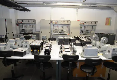
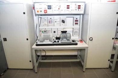
The Electrical Machines Laboratory is a laboratory in which Electrical and Electronics Engineering students can carry out various experiments in order to grasp the fundamental principles and processes involved in converting mechanical energy into electrical energy and electrical energy into mechanical energy. Through the experiments conducted in the laboratory, concepts such as DC, AC, three-phase, single-phase, generator and transformer are understood through practice and practical skills are acquired.
Through a variety of experiments on electromechanical energy conversion, the operating principles and mathematical models of DC machines, synchronous machines, transformers, induction machines and other electromechanical components, the aim is for students to acquire the necessary and sufficient skills.
Experiments:
- DC Machine Structure, Operation and Basic Experiments
- DC Shunt Machine and Its Experiments
- DC Series Machine and Its Experiments
- DC Compound Machine and Its Experiments
- Parallel Connection of Dynamos and Related Experiments
- Torque and Power in DC Motors
- Single-Phase Transformers and Their Experiments
- Three-Phase Transformers and Their Experiments
- Parallel Connection of Transformers
- Autotransformers and Their Experiments
- Instrument Transformers and Their Experiments
- Three-Phase Induction Motor Experiments
- The D-LAB Computer Interface and Its Use
- Single-Phase Induction Motor, EASY Relay Experiments and Stepper Motor
- Synchronous Machine and Its Experiments
Laboratory Facilities:
Three-phase fuse, multimeters, DC measurement unit, AC measurement unit, resistor module, 500Ω-100W rheostat module, inductive module, capacitive module, load module, three-phase phase-sequence indicator module, magnetic particle brake, motor drives, synchroscope, frequency meter, rheostat, three-phase phase-sequence indicator module, single-phase induction motor, three-phase induction motor, DC compound machine, DC shunt machine, transformer module (single-phase, 55V - 110V - 220V output), transformer module (three-phase, 55V - 110V - 220V output).
Laboratory Coordinator: Assist. Prof. Dr. Mohammed JOUDA
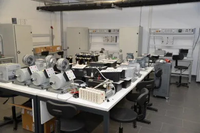
Power electronics is the technology concerned with the efficient conversion, control and conditioning of electric power by static means from its available input form into the desired electrical output form. Power electronics converters can be used wherever electrical energy needs to change form. In the Power Electronics Laboratory, various experiments are carried out on the operating principles and characteristics of semiconductor power electronics components, the analysis of switching circuits, converters, rectifiers, inverters, choppers and frequency converters. As a result of the experiments conducted in the Power Electronics Laboratory, our students gain a better understanding of the role of power electronics in a range of technological applications, such as industrial systems, households, communication systems, transport systems and facilities.
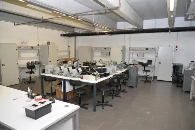
Experiments: Deriving diode characteristics, thyristors, forward blocking test, reverse blocking test, forward breakover test of the thyristor, forward conduction test, MOSFET turn-on test, MOSFET switching test, IGBT turn-on test, IGBT switching test, single-phase half-wave rectifier, single-phase full-wave rectifier, three-phase half-wave rectifier, three-phase bridge rectifier, thyristor rectifiers, AC voltage control, reverse dimmer experiment, DC-DC converters, three-phase inverters, single-pulse amplitude modulation, multi-pulse amplitude modulation, modified sinusoidal multi-pulse amplitude modulation, three-phase motor control and its implementation with D-LAB.
Laboratory Facilities: Oscilloscopes, power supplies, multimeters, diode module, reference voltage module, single-phase control unit, measurement unit, three-phase fuse, resistor module, D-LAB, three-phase inverter, 100Ω-200W rheostat module, inductive module, capacitive module, triac module, snubber module, thyristor module, DC-DC boost converter module, three-phase control unit, DC-DC buck converter module, switching module, three-phase induction module, load module.
Laboratory Coordinator: Assist. Prof. Dr. Mohammed JOUDA
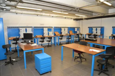
In this laboratory, which will provide hands-on experience for Faculty of Engineering students, Electrical and Electronics Engineering students in particular will carry out tests in the field of communication technologies and learn the methods for measuring parameters relating to transmission lines, waveguides and antennas. They will acquire the ability to design, analyse and implement antennas. In addition, they will learn analogue and digital modulation types and grasp the operating logic of the receiver and transmitter parts of a communication system.
They will also carry out laboratory experiments on the propagation of electromagnetic waves, amplitude modulation and demodulation, frequency modulation and demodulation, time-division multiplexing and so on.
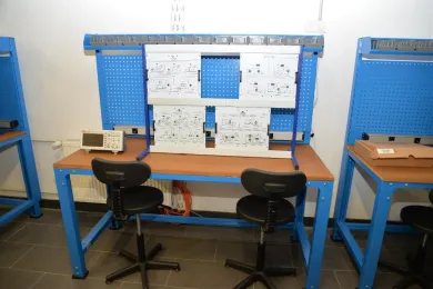
Experiments:
- Series Hartley - Parallel Hartley
- Study of Amplitude Modulation (AM)
- Study of Amplitude Modulation (AM-DSB)
- Colpitts Oscillator
- Demodulation of Amplitude Modulation with an Asynchronous Diode Detector
- Study of Amplitude Modulation (DSB - Double Side Band)
- Study of the Operation of a Low-Pass Active Filter
- Frequency Modulation
- Study of the PLL (Phase Locked Loop) -1
- Study of the PLL (Phase Locked Loop) -1
Laboratory Facilities:
Analogue-to-digital converter, PWM, ASK modulator & demodulator, FSK modulator & demodulator, PSK modulator & demodulator, delta encoder & decoder, FDM encoder & decoder, TDM encoder & decoder, oscillators, amplitude modulator & demodulator, frequency modulator & demodulator, manuals, oscilloscopes, measuring instruments.
Laboratory Coordinator: Assist. Prof. Dr. Motuma Muktar ABAFOGI
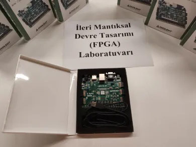
FPGA is the abbreviation of Field Programmable Gate Array. These devices are programmable logic devices. FPGAs are built by combining digital logic, memory, processor cores and other customised components. They are used for the hardware implementation of customised digital circuits and offer a faster and cheaper alternative to ASIC (Application-Specific Integrated Circuit) design.
The Advanced Logic Circuit Design (FPGA) Laboratory is an educational programme designed to help students gain in-depth knowledge and practical skills in digital circuit design and FPGA technology. The laboratory allows theoretical knowledge to be reinforced through applied projects and enhances students' competence in modern digital system design.
Experiments:
- Field Programmable Gate Arrays (FPGAs)
- Xilinx Artix 7.
- Programming FPGAs.
- Constraint Editor, Static Timing Analysis.
- Debugging FPGA Design.
- VHDL Examples
- Combinational Logic Design
- Multilevel Combinational Logic.
- Combinational Building Blocks.
- Timing.
- Hardware Description Languages (HDL) for Combinational Logic
- Multiplexers
- 7-Segment Displays VHDL Examples
- Code Converters
- Decoders and Encoders
- Digital Building Blocks and Arithmetic Circuits
- Arithmetic Circuits
- Adders, Half Adder, Full Adder,
- Subtractors, Half Subtractor, Full Subtractor
- Shifters
- Multiplication
- Division
- Arithmetic Logic Unit (ALU)
- Sequential Logic Design
- Latches and Flip-Flops
- Synchronous Logic Design.
- Registers
- Shift Registers
- Counter
- Pulse Width Modulation
- Finite State Machines
- Mealy and Moore outputs
- A Moor Machine Sequence Detector
- Example - Door Lock Code
- Example- Traffic Lights
Laboratory Facilities and Features:
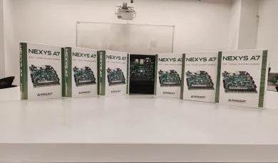
Nexys A7-100T Artix-7 FPGA board
| Product Variant | Nexys A7-100T |
| FPGA Part Number | XC7A100T-1CSG324C |
| Look-up Tables (LUTs) | 63,400 |
| Flip-Flops | 126,800 |
| Block RAM | 1,188 Kb |
| DSP Slices | 240 |
| Clock Management Tiles | 6 |
Laboratory Coordinator: Assist. Prof. Dr. Mohammed JOUDA
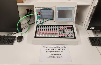
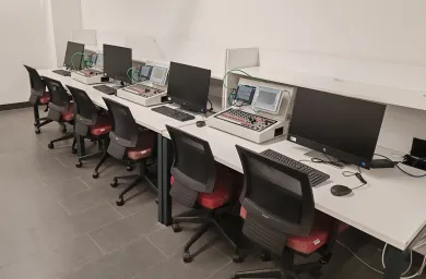
A PLC (Programmable Logic Controller) is a programmable device used in automation systems. It is designed to automate industrial processes and machinery. PLCs receive input data and carry out output operations according to a defined logic or programme. The PLC Programming and Automation Laboratory is an educational programme designed to help students gain comprehensive knowledge and practical experience in industrial automation systems and Programmable Logic Controllers (PLCs). The laboratory enables students to reinforce their theoretical knowledge through applied projects and to develop competence in the field of industrial automation. In this laboratory, students and participants are taught subjects such as the fundamentals of modern automation systems, the operation and programming of PLCs, and the use of sensors and actuators.
Experiments:
- Review of general digital electronics concepts
- Number and coding systems
- Explanation of the Bit, Byte, Word and Doubleword concepts
- Siemens S7 PLCs
- Components of a PLC
- PLC input-output units (signal modules-cards) (S7-1200 PLC I/O modules and configuration)
- Differences between the S7-200 and S7-1200 PLCs
- Programming software (programming interface) – (Introduction to TIA Portal software)
- Address areas used in the PLC
- Number systems
- Linear program processing
- S7-1200 hardware structure and hardware configuration, Device Configuration menu
- Addressing of PLC modules
- Program coding formats - ladder diagram (Ladder Diagram - LAD), function block diagram (Function Block Diagram: FBD), working logic of LAD/FBD programming
- Creating a project for the S7-1200 with TIA Portal
- Uploading the project on the PLC into the TIA Portal project (upload)
- Creating OB and FC, Download operation, Taking a backup
- Taking an online back-up with TIA Portal
- Backing up the project on the PC and restoring it from the backup
- Licensing procedures for "SIMATIC" programs
- Screen layouts in TIA Portal
- Logic Functions
- Programming Instructions, Bit Logic
- Internal memory areas
- Memory function, Mutual interlocking of memory elements
- S7-1200 simulator
- TIMER function
- Counter function
- Fundamentals of PLC Programming
- Circuit Design and Ladder Programming
- Data Transfer and Comparison
- Mathematical Operations
- Project monitoring and modification
- Application solutions
Laboratory Facilities and Features:
- PLC Training Set
- S7 1200 PLC
- KTP 700 Option
- EASYPORT Interface
Laboratory Coordinator: Assist. Prof. Dr. Mohammed JOUDA
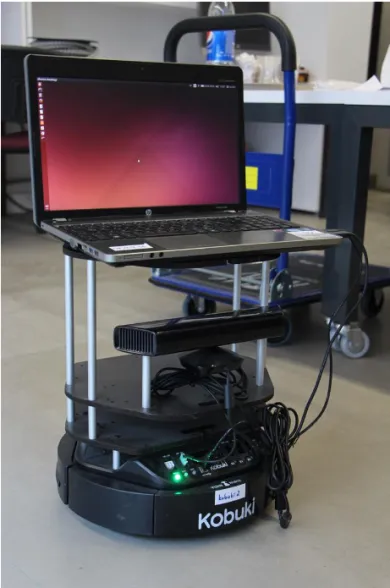
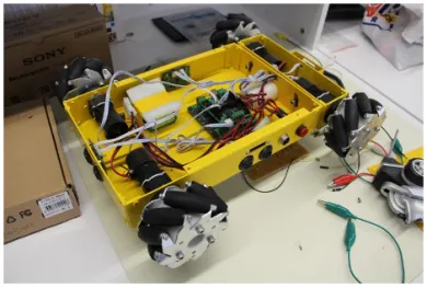
In the Robotics Laboratory, undergraduate and graduate students can carry out research on their thesis topics and complete their work by conducting experiments on real robotic systems. In the Robotics and Control Laboratory, students can design their own robots in 3D design programs and print them out with the 3D printers available in the laboratory. With these printed parts they can assemble the mechanical sections of their robots and bring them to life with electronic development boards.
Experiments:
- P Control
- PI Control
- PD Control
- PID Control
- Speed Control
- Position Control
- Trajectory Planning
- Obstacle and Collision Avoidance
Laboratory Facilities:
- Drones
- Turtlebot-2s
- Festo Robotino
- Omni wheels
- Mecanum wheels
- Standard wheels
- Arduino boards of various types and their shields
- Raspberry Pi, Raspberry Pi 3
- Jetson
- Robot development kits
- Oscilloscopes
- Multimeters
- Signal generators
- Basic electronic components (resistors, transistors, integrated circuits, etc.)
- Soldering guns, soldering irons, soldering bench, heat gun
- Cable, heat-shrink tubing, etc.
- Matlab
- ROS
- Gazebo
Laboratory Facilities:
Three-phase fuse, multimeters, DC measurement unit, AC measurement unit, resistor module, 500Ω-100W rheostat module, inductive module, capacitive module, load module, three-phase phase-sequence indicator module, magnetic particle brake, motor drives, synchroscope, frequency meter, rheostat, three-phase phase-sequence indicator module, single-phase induction motor, three-phase induction motor, DC compound machine, DC shunt machine, transformer module - single-phase with 55V - 110V - 220V output, transformer module - three-phase with 55V - 110V - 220V output.
Laboratory Coordinator: Assist. Prof. Dr. Mohammed JOUDA


